Voltage Drop Calculator
NEC voltage drop calculator. Enter system, voltage, current, one-way length and conductor, and get volts dropped, percent drop, voltage at the load and the smallest conductor that meets your target.
Interactive tool
Presets
Circuit
Result
What is the Voltage Drop Calculator?
Every conductor has resistance, so the voltage arriving at a load is always lower than the voltage leaving the panel. This calculator works out how much lower. Give it the system (DC, single-phase or three-phase), the source voltage, the load current, the one-way run in feet and the conductor, and it returns volts dropped, drop as a percentage, the voltage actually present at the load, and the smallest conductor that would bring the run inside your target. Resistance comes from NEC Chapter 9 Table 8, which is the same table an electrician would open.
How to Use the Voltage Drop Calculator
- 1Pick the system: DC and single-phase both use a factor of 2, three-phase uses the square root of 3
- 2Enter the nominal source voltage, for example 120, 240, 277 or 480
- 3Enter the load current in amperes, not the breaker size
- 4Enter the one-way length of the run. The return path is already in the multiplier, so do not double it yourself
- 5Choose copper or aluminum, and the conductor size
- 6Set your drop target if 3% is not what you are working to, and read off the smallest size that meets it
Key features
NEC Table 8 resistance
The same DC resistance values at 75 °C that the code book carries, not a generic constant
Solid and stranded
Table 8 lists them separately and they differ by about 2%. Both are selectable
Three systems
DC, single-phase and three-phase, with the correct multiplier applied to each
Parallel sets
Two sets halve the effective resistance. Enter the set count and the maths follows
Smallest size that fits
Walks every size from 14 AWG to 1000 kcmil and names the first one inside your target
Copper and aluminum
Aluminum is roughly 60% more resistive at the same size, which the results make plain
Why Voltage Drop Matters
A load that is 8% low does not usually announce itself. Motors run hotter and produce less torque, because torque falls with the square of the voltage. Resistive heaters take longer and never quite reach temperature. LED drivers flicker or drop out at the bottom of their input range. Contactors chatter. None of these read as a wiring fault, so they get chased as equipment faults for a long time before anyone measures the voltage at the load with the load running. Sizing for drop at design time costs one conductor size and avoids all of it.
Common use cases
- Size a feeder to a detached garage or workshop at the far end of a property
- Check whether an existing circuit explains a motor that runs hot and low on torque
- Work out how far a 20 A branch circuit can run on 12 AWG before it breaks 3%
- Compare copper against aluminum for a long service run where cost matters
- Decide whether paralleling two smaller sets beats one larger conductor
- Verify a low-voltage DC run, where drop is proportionally far more punishing
The formula
- For DC and single-phase: volts dropped = 2 × I × R × L / 1000, where I is amperes, R is the conductor resistance in ohms per 1000 feet, and L is the one-way length in feet. The factor of 2 is there because the current travels out along one conductor and back along another, so the copper in the circuit is twice the run.
- For three-phase: volts dropped = 1.732 × I × R × L / 1000. The square root of 3 is not a physical doubling. It falls out of the phase relationship between line-to-line voltages, and it is why a three-phase run drops noticeably less than a single-phase run of the same length and current.
- Percentage drop is simply the volts dropped divided by the nominal source voltage. Note that the percentage, not the absolute volts, is what the guidance is written against: 6 volts is trivial on a 480 V feeder and severe on a 12 V DC run.
Why 3% is a recommendation, not a rule
- The familiar figures are 3% on a branch circuit and 5% total including the feeder. They appear in NEC 210.19(A) and 215.2(A), but they appear there as Informational Notes. Informational Notes are explanatory and are not enforceable code text, which means an inspector cannot fail a run on drop alone under the base NEC.
- That is not permission to ignore them. Many jurisdictions amend the code to make the figures mandatory, some load types have their own requirements elsewhere in the code, and the performance problems that drop causes are real regardless of what is enforceable. Treat 3% as a design target you should have a reason to miss, and check your local amendments rather than assuming the base code applies as written.
What this calculator does not model
- It uses DC resistance from Chapter 9 Table 8 and ignores reactance. For branch circuits and small feeders that is the ordinary method and the error is small. On large conductors, long runs, or loads with a power factor well below 1, the reactive term stops being negligible and Chapter 9 Table 9 is the correct basis instead. Table 9 also varies with the conduit material, because a steel raceway raises reactance in a way PVC does not.
- It uses the 75 °C resistance values. A conductor running hot is more resistive than that and will drop slightly more; one running cool will drop slightly less. Table 8 is stated at 75 °C and that is the figure the code book carries, so it is the figure used here.
- It does not size the conductor for ampacity. Drop and ampacity are separate limits and neither substitutes for the other. A conductor can be thermally fine and still drop far too much, which is the usual outcome on a long run. Use the wire size calculator to satisfy both at once.
Copper against aluminum
- Aluminum is about 61% more resistive than copper at the same size, so an aluminum conductor drops that much more over the same run. The usual rule of thumb is to go up two sizes when substituting aluminum for copper, and the numbers here bear that out: 4/0 aluminum at 0.1 ohms per 1000 feet sits between 2/0 copper at 0.0967 and 1/0 copper at 0.122.
- Aluminum is still often the right answer on long feeders and services, where it is substantially cheaper per amp delivered even after the size increase. Where it is usually the wrong answer is on branch circuits, both because the size penalty bites harder at small sizes and because terminations need more care.
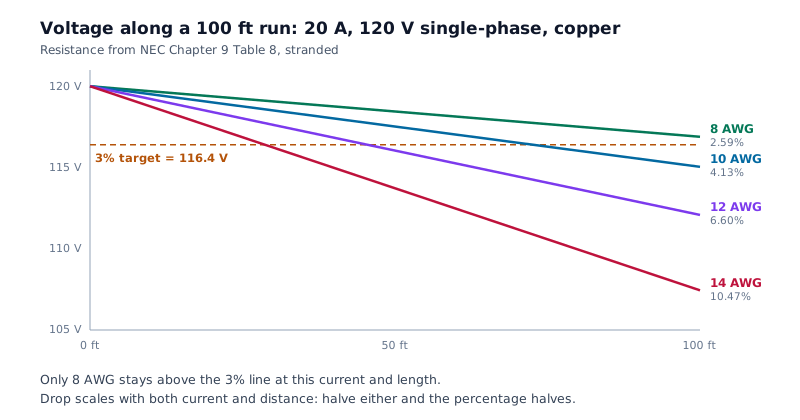
Voltage drop at 20 A over a 100 foot run, 120 V single-phase
Stranded copper, computed from NEC Chapter 9 Table 8. Note where the 3% target falls: at this current and length, 12 AWG is already well past it, and the first size that comfortably clears is 8 AWG.
| Size | Resistance (Ω per 1000 ft) | Drop (V) | Drop (%) | Within 3% |
|---|---|---|---|---|
| 14 AWG | 3.14 | 12.56 | 10.47% | No |
| 12 AWG | 1.98 | 7.92 | 6.60% | No |
| 10 AWG | 1.24 | 4.96 | 4.13% | No |
| 8 AWG | 0.778 | 3.11 | 2.59% | Yes |
| 6 AWG | 0.491 | 1.96 | 1.64% | Yes |
| 4 AWG | 0.308 | 1.23 | 1.03% | Yes |
Drop scales linearly with both current and length, so the same 12 AWG run at 10 A, or at 50 feet, drops half as much and lands at 3.30%.
Tips & best practices
Use the load, not the breaker
Enter the actual load current. Sizing drop against a 20 A breaker feeding a 6 A load buys copper nobody needs.
The length field is one-way
The return conductor is already in the multiplier. Entering the round-trip length doubles the answer.
Three-phase means line-to-line
Use 208, 480 or 600, not the line-to-neutral figure. The root-three multiplier already assumes it.
Voltage beats copper on a bad run
Doubling the supply voltage quarters the percentage drop at the same power. On a run that fails badly, that is usually cheaper than two conductor sizes.
Check ampacity separately
Drop and ampacity are independent limits. A conductor can clear 3% comfortably and still be too small thermally, or the reverse.
Privacy & security
Every calculation runs in your browser. Nothing about your circuit, your load or your project is uploaded, stored or logged.
Frequently asked questions
How do you calculate voltage drop?
+
For DC and single-phase, volts dropped = 2 × I × R × L / 1000, where I is the load current in amperes, R is the conductor resistance in ohms per 1000 feet, and L is the one-way length in feet. For three-phase, replace the 2 with 1.732, the square root of 3. Divide the result by the source voltage for percentage drop. This calculator takes R from NEC Chapter 9 Table 8.
What is an acceptable voltage drop?
+
The commonly used design targets are 3% on a branch circuit and 5% total including the feeder. Those figures come from the NEC and they are what most engineers and inspectors expect to see, even though the base code states them as recommendations rather than requirements.
Is the 3% voltage drop rule actually a code requirement?
+
Not in the base NEC. The 3% and 5% figures appear in Informational Notes attached to 210.19(A) and 215.2(A), and Informational Notes are explanatory rather than enforceable. Many local jurisdictions amend the code to make them mandatory, and specific applications elsewhere in the code have their own limits, so check your local amendments rather than assuming the base text applies.
How far can I run 12 AWG on a 20 amp circuit?
+
At 20 A on a 120 V single-phase circuit, 12 AWG stranded copper hits 3% at about 45 feet one-way. At 240 V the same conductor and current reaches roughly 91 feet, because the percentage is taken against a voltage twice as large. Both figures assume the full 20 A: a lighter actual load runs proportionally further.
Why does a three-phase circuit drop less than single-phase?
+
The multiplier is 1.732 rather than 2, so at the same current, length and conductor a three-phase run drops about 13% less. It is not that less current flows. The difference comes from the phase relationship between the line-to-line voltages, which is also why you use the line-to-line figure, 208 or 480, and not the line-to-neutral one.
Does aluminum wire drop more voltage than copper?
+
Yes, about 61% more at the same size, because aluminum is more resistive. The usual answer is to go up roughly two sizes when substituting aluminum for copper. On long feeders and services aluminum is often still the better value even after the size increase; on branch circuits the penalty tends to outweigh the saving.
Should I enter the one-way length or the total wire length?
+
One-way. The return conductor is already accounted for in the multiplier, which is exactly what the factor of 2 in the single-phase formula represents. Entering the round-trip length doubles the answer.
Does this calculator account for power factor?
+
No. It uses DC resistance from Chapter 9 Table 8 and ignores reactance, which is the ordinary method and is accurate for branch circuits and small feeders. On large conductors, long runs or loads with a power factor well below 1, reactance matters and Chapter 9 Table 9 is the correct basis. The results say so rather than implying a precision the method does not have.
Related tools
- Voltage Divider Calculator
Calculate the output voltage, current, and power of a resistive voltage divider with optional load. Highlights loading effects when the load is too small.
Electronics & Embedded
- Cable Tray Fill Calculator
NEC 392.22 cable tray fill check for ladder, ventilated, and solid-bottom trays. Sums cable areas / diameters and reports pass/fail with the right rule citation.
Electronics & Embedded
- RC Time Constant Calculator
Compute the time constant τ = R × C, plot the charge or discharge curve, and find the time to reach a target voltage for any RC circuit.
Electronics & Embedded
- Signal Attenuation (dB) Calculator
Convert between power / voltage ratios and dB, compute Free-Space Path Loss (FSPL), and estimate cable attenuation. Supports forward and reverse calculations.
Electronics & Embedded
- ADC / DAC Converter Calculator
Convert between analog voltage and digital code for any N-bit ADC or DAC. Computes LSB size, quantisation error, full-scale range, and ideal dynamic range (SQNR).
Electronics & Embedded
- Capacitor Charge & Energy Calculator
Compute the stored charge (Q = CV) and energy (E = ½ CV²) of a charged capacitor, with intuitive real-world comparisons.
Electronics & Embedded