Voltage Divider Calculator
Calculate the output voltage, current, and power of a resistive voltage divider with optional load. Highlights loading effects when the load is too small.
Interactive tool
Presets
Inputs
Resistance inputs accept engineering notation (10k, 4.7M).
Result
What is the Voltage Divider Calculator?
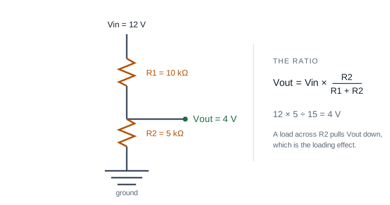
A voltage divider is two resistors in series that split a supply voltage into a fraction. This tool computes the output voltage, the current drawn from the source, and the power dissipated in each resistor, with an optional load resistor that exposes the loading effect explicitly.
How to Use the Calculator
- 1Enter the input voltage Vin
- 2Enter R1 (top resistor) and R2 (bottom resistor, Vout taken across this one)
- 3Optionally enable the load resistor RL and enter its value to model a real circuit
- 4Read off Vout, divider current, power per resistor, and any loading warning
Key features
Loaded and unloaded
Optional load resistor in parallel with R2; the tool shows the effective lower-leg resistance and the loading error percentage
Engineering notation
Inputs and outputs use SI prefixes (kΩ, MΩ, mV)
Power per resistor
Helps you pick wattage ratings and spot bad designs that burn resistors
Loading warning
Highlights when the load is small enough (>10% loading) to materially change Vout from the unloaded value
Common presets
5→ 3.3 V, 12→ 5 V, even-split, and loaded divider examples
Live evaluation
Results update as you type: no submit button
Why a Loaded Voltage Divider Calculator?
The classic Vout = Vin × R2 / (R1 + R2) ignores the load, which is fine for high-impedance loads like an op-amp input. But the moment you connect anything that draws current: a microcontroller ADC pin with low input impedance, a digital input with internal pull-up, or another stage of analog electronics, the divider can sag dramatically. Modeling RL explicitly catches that class of bug before you wire the circuit.
Common use cases
- Scale a high voltage down to a microcontroller’s 0 to 3.3 V ADC input
- Build a level shifter from 5 V logic to 3.3 V (with loading-effect awareness)
- Create a reference voltage for an op-amp comparator or DAC
- Estimate the current burden of a fixed-bias circuit on the supply
- Sanity-check a divider on an existing PCB against measured values
- Teach the loading effect to students using a real interactive example
Formulas
- Unloaded: Vout = Vin × R2 / (R1 + R2)
- Loaded: R2_eff = R2 ∥ RL = (R2 × RL) / (R2 + RL); Vout = Vin × R2_eff / (R1 + R2_eff)
- Divider current: I = Vin / (R1 + R2_eff)
- Loading error: (Vout_unloaded − Vout_loaded) / Vout_unloaded
Rule of thumb
Pick R2 ≤ (1/10) × RL to keep loading below ~10%. For ADC inputs with 1 to 10 MΩ impedance, divider resistances up to ~100 kΩ are typically fine. For high-impedance op-amp inputs, you can use much larger resistors and save quiescent current.
Tips & best practices
Trade-off: precision vs current
Small resistors give crisp, low-impedance dividers but waste current. Large resistors save power but pick up noise and load down easily. 10 kΩ to 100 kΩ covers most logic-level use cases.
Use the optional load when modeling reality
For a 1 MΩ ADC, the load is irrelevant; for a 5 kΩ op-amp input bias, it matters. Always model the actual downstream impedance for tight precision.
Tolerance accumulates
Two 5% resistors don’t give a 5% Vout error; in the worst case you can see ~10%. For precision references, use 1% (E96) or better.
Privacy & security
Everything runs in your browser; no values leave your device.
Related tools
- UPS Runtime Calculator
Estimate UPS / battery-backup runtime from battery voltage, capacity, series / parallel arrangement, load wattage, inverter efficiency, and depth of discharge. Includes a Peukert warning at high discharge rates.
Electronics & Embedded
- Transformer Sizing Calculator
Compute required transformer kVA from connected load, power factor, future growth, K-factor (harmonics), and ambient derating. Picks the next NEMA standard rating.
Electronics & Embedded
- Generator Sizing Calculator
Size a standby or prime generator from continuous load, largest motor (HP + NEMA code letter + start method), altitude and ambient derating. Picks the next standard kW rating.
Electronics & Embedded
- Power Calculator (DC, AC, 3-Phase)
Compute real, apparent, and reactive power for DC and AC circuits including single-phase and three-phase systems with adjustable power factor.
Electronics & Embedded
- PWM Duty & Frequency Calculator
Solve any unknown of a PWM waveform: frequency, period, duty cycle, on-time, off-time. Optional supply voltage gives average and RMS voltage. Inline waveform preview.
Electronics & Embedded
- Short Circuit Current Estimator
Educational point-to-point estimator for available short-circuit current from a transformer secondary, with optional cable attenuation. Not a replacement for IEEE 1584 or utility-provided fault values.
Electronics & Embedded
Frequently Asked Questions
What is the voltage divider formula?
For two resistors R1 (top) and R2 (bottom) in series across Vin, with Vout taken across R2: Vout = Vin × R2 / (R1 + R2). With a load resistor RL in parallel with R2, replace R2 by the parallel combination R2 ∥ RL = (R2 × RL) / (R2 + RL).
What is the loading effect?
When you connect a load to a divider, the load draws current that pulls the output voltage below the unloaded value. The loading effect is the percentage drop. As a rule of thumb, keep the load resistance at least 10× R2 to keep the error under ~10%.
Why does the tool show power dissipation?
Tiny resistors dissipate non-trivial power on high-voltage rails. A 100 Ω / 100 Ω divider on 24 V drops about 2.9 W total: way too much for typical 1/4 W resistors. The dissipation field warns you before smoke happens.
Can I use a voltage divider as a voltage regulator?
Only for very light loads. A resistive divider has no output regulation: a change in load current changes Vout. For real regulation, use an LDO, switching regulator, or zener-buffered design. Dividers are perfect for fixed references into high-impedance inputs (ADCs, op-amps, comparators).
Why does increasing R1 or R2 reduce dissipation?
The current through an unloaded divider is I = Vin / (R1 + R2). Power dissipated is Vin × I = Vin² / (R1 + R2). Larger resistors mean less wasted power but more sensitivity to loading.
Is anything sent to a server?
No: everything runs in your browser. No values, results, or interactions are uploaded.