RC Time Constant Calculator
Compute the time constant τ = R × C, plot the charge or discharge curve, and find the time to reach a target voltage for any RC circuit.
Interactive tool
Presets
Inputs
Result
What is the RC Time Constant Calculator?
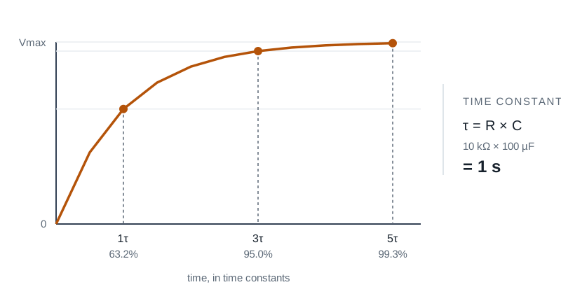
A resistor-capacitor (RC) network is the simplest first-order analog filter. Its dynamics are governed by a single number: the time constant τ = R × C. This tool computes τ, plots the charge or discharge curve over 5τ, and finds the exact time required to reach an arbitrary target voltage.
How to Use the Calculator
- 1Enter R and C using engineering notation (e.g. 10k, 100n)
- 2Pick Charge or Discharge mode
- 3Enter the reference voltage (Vmax for charging, V0 for discharging)
- 4Optionally enter a target voltage to compute the exact time to reach it
- 5Read τ, the multi-τ markers (63%, 86%, 95%, 98%, 99.3%), and the curve plot
Key features
Live charge & discharge curves
A 121-sample plot covering 5τ of the trajectory
τ markers
Highlights the canonical 1τ, 2τ, 3τ, 4τ, 5τ voltage levels for quick reference
Time to target
Optional target voltage → exact time t = −τ ln(…)
Engineering notation
Inputs and outputs use SI prefixes (kΩ, µF, ms, µs, ns)
Useful presets
Common RC values for debounce, filtering, and PSU smoothing
100% private
All math and plotting runs in your browser
Why a Dedicated RC Calculator?
Almost every analog circuit: from a button debounce to a sample-and-hold to a low-pass anti-aliasing filter, contains an RC network. Memorising τ = R × C is easy. Computing the exact time to reach a specific threshold (e.g. the logic switching point of an input) is annoying because of the natural log. Pre-computing the multi-τ percentages and plotting the curve takes the guesswork out.
Common use cases
- Size a debounce RC for a mechanical switch into a digital input
- Pick a low-pass RC filter’s cutoff (τ = 1 / (2π f_c))
- Estimate how long a power supply rail will hold after the regulator shuts off
- Compute the dead time before a microcontroller’s pulled-up input crosses VIH
- Model the rise time of a long signal trace driven through a series resistor
- Teach exponential settling and the 5τ rule of thumb
Formulas
- τ = R × C
- Charging: V(t) = Vmax × (1 − e⁻ᵗᐟᵀ)
- Discharging: V(t) = V0 × e⁻ᵗᐟᵀ
- Charge time to fraction f: t = −τ ln(1 − f)
- Discharge time to fraction f: t = −τ ln(f)
The 5τ rule
Engineers use 5τ as the practical "fully settled" time: the voltage is within 0.7% of its final value. Anything beyond 5τ is dominated by leakage, dielectric absorption, and instrument noise. For tight settling specs (10․16-bit DAC settling, for example) use 7 to 10τ.
Tips & best practices
Cutoff frequency conversion
For an RC low-pass filter, the −3 dB cutoff is f_c = 1 / (2πRC). τ in seconds and f_c in hertz are related by τ = 1 / (2π f_c).
Source resistance matters
The "R" in your circuit is everything the cap charges through: driver output impedance, series resistors, PCB trace resistance. Use a measured value, not just the nominal resistor.
Pick caps with low ESR for sharp transitions
Electrolytic caps have non-negligible ESR that can dominate at very short τ. Use ceramics or film caps for fast switching nodes.
Privacy & security
All math runs in your browser. No values leave your device.
Related tools
- Transformer Sizing Calculator
Compute required transformer kVA from connected load, power factor, future growth, K-factor (harmonics), and ambient derating. Picks the next NEMA standard rating.
Electronics & Embedded
- Generator Sizing Calculator
Size a standby or prime generator from continuous load, largest motor (HP + NEMA code letter + start method), altitude and ambient derating. Picks the next standard kW rating.
Electronics & Embedded
- Voltage Divider Calculator
Calculate the output voltage, current, and power of a resistive voltage divider with optional load. Highlights loading effects when the load is too small.
Electronics & Embedded
- PWM Duty & Frequency Calculator
Solve any unknown of a PWM waveform: frequency, period, duty cycle, on-time, off-time. Optional supply voltage gives average and RMS voltage. Inline waveform preview.
Electronics & Embedded
- Short Circuit Current Estimator
Educational point-to-point estimator for available short-circuit current from a transformer secondary, with optional cable attenuation. Not a replacement for IEEE 1584 or utility-provided fault values.
Electronics & Embedded
- Cable Tray Fill Calculator
NEC 392.22 cable tray fill check for ladder, ventilated, and solid-bottom trays. Sums cable areas / diameters and reports pass/fail with the right rule citation.
Electronics & Embedded
Frequently Asked Questions
What is the RC time constant?
τ = R × C, in seconds when R is in ohms and C in farads. It is the time for the voltage to traverse 1 − 1/e (~63.2%) of the gap between its current value and its final value.
Why is 5τ "fully settled"?
After 5 time constants, the voltage is within e⁻⁵ ≈ 0.67% of its final value: close enough for almost any practical purpose. Beyond 5τ, error is usually dominated by leakage, ESR, or measurement noise rather than the RC exponential.
How do I convert τ to a filter cutoff?
For a first-order RC low-pass, the −3 dB cutoff frequency is f_c = 1 / (2πRC) = 1 / (2πτ). For a 10 kHz cutoff, τ ≈ 15.9 µs: e.g. 1 kΩ with 16 nF, or 10 kΩ with 1.6 nF.
Does this assume an ideal step input?
Yes. The model assumes an ideal voltage source switching at t = 0 to Vmax (charge) or from V0 to 0 (discharge). For real drive impedances, add them in series with R for an accurate τ.
What about leakage resistance?
Long discharges (large RC) are sensitive to capacitor leakage and PCB insulation resistance, which the ideal model ignores. If your measured discharge ends well below 0, leakage is likely dominating; for hold-time circuits, use low-leakage caps and clean boards.
Is anything sent to a server?
No. All math, plotting, and rendering happens in your browser. Nothing is uploaded.