Signal Attenuation (dB) Calculator
Convert between power / voltage ratios and dB, compute Free-Space Path Loss (FSPL), and estimate cable attenuation. Supports forward and reverse calculations.
Interactive tool
Inputs
Result
What is the Signal Attenuation Calculator?
A unified decibel calculator covering the four most common cases: power ratios, voltage ratios, free-space path loss, and cable attenuation. Plus a reverse mode that converts a dB figure back into a linear voltage or power ratio.
How to Use the Calculator
- 1Pick a mode: Power, Voltage, FSPL, Cable, or Reverse
- 2Power / voltage: enter the two values; the calculator returns dB and the ratio
- 3FSPL: enter distance in km and frequency in GHz; returns total path loss
- 4Cable: enter length in metres and attenuation in dB/m; preset chips for common cables
- 5Reverse: enter a dB value and pick power or voltage; returns the linear ratio
Key features
Five modes in one tool
Power, voltage, FSPL, cable, and reverse dB → ratio
Common cable presets
CAT5e, CAT6, RG-58, LMR-400, SMF fiber: one click to fill dB/m
Engineering notation
All numeric inputs accept k, M, m, µ, n prefixes
Forward and reverse
Round-trip seamlessly between dB and linear ratio
Nepers output
For audio / control-systems work where Np is the native unit
Live evaluation
Updates as you type: no submit button
Why a Signal Attenuation Calculator?
dB math is everywhere in RF, audio, optical, and instrumentation work, and it’s easy to slip a factor of two between voltage and power formulas. This tool keeps the formulas separate, labels them, and gives a per-mode ratio so you can sanity-check the order of magnitude before relying on it.
Common use cases
- Compute path loss for a 2.4 GHz link at 1 km (≈97 dB)
- Estimate the dB drop across a 100 m run of LMR-400 at 1 GHz
- Convert a 60 dB amplifier voltage gain to a linear ratio
- Verify a power-divider insertion loss against its specification
- Translate a vendor’s dB spec into something you can multiply
Formulas
- Power ratio: dB = 10 · log₁₀(P₁ / P₂)
- Voltage ratio: dB = 20 · log₁₀(V₁ / V₂)
- FSPL: dB = 20 · log₁₀(d_km) + 20 · log₁₀(f_GHz) + 92.45
- Cable: dB = length(m) × dB/m
- Reverse voltage: ratio = 10^(−dB / 20)
- Reverse power: ratio = 10^(−dB / 10)
- Nepers: Np = dB / 8.686
When voltage vs power matters
In a fixed-impedance system (50 Ω RF, 600 Ω audio), the 20·log10 voltage formula and the 10·log10 power formula give the same dB number, because V and √P scale together. Confusion happens when measuring across mismatched impedances; in that case use the underlying power explicitly.
Tips & best practices
Three-dB rule of thumb
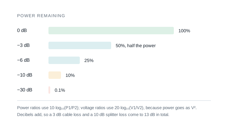
+3 dB doubles power. −3 dB halves it. +10 dB is 10× power. +20 dB is 100× power. These four numbers cover most quick estimates.
FSPL is an idealisation
Real radio links also lose to terrain, foliage, atmospheric absorption, and antenna mismatch. FSPL is the floor; real-world path loss is higher.
Cable spec is frequency-dependent
Coax attenuation goes up with the square root of frequency. The presets in the tool list the dB/m at one frequency: always check the cable’s datasheet for the frequency you care about.
Privacy & security
Everything runs in your browser; no values leave your device.
Related tools
- 555 Timer Calculator
Design an NE555 astable oscillator or monostable one-shot. Pick R1, R2, C and read off frequency, period, duty cycle, and pulse width, with an inline schematic.
Electronics & Embedded
- UPS Runtime Calculator
Estimate UPS / battery-backup runtime from battery voltage, capacity, series / parallel arrangement, load wattage, inverter efficiency, and depth of discharge. Includes a Peukert warning at high discharge rates.
Electronics & Embedded
- Power Factor Correction Calculator
Compute kVAR and capacitance per phase needed to raise an installation from its current power factor to a target. Before/after power-triangle diagram and current-reduction estimate.
Electronics & Embedded
- Transformer Sizing Calculator
Compute required transformer kVA from connected load, power factor, future growth, K-factor (harmonics), and ambient derating. Picks the next NEMA standard rating.
Electronics & Embedded
- Generator Sizing Calculator
Size a standby or prime generator from continuous load, largest motor (HP + NEMA code letter + start method), altitude and ambient derating. Picks the next standard kW rating.
Electronics & Embedded
- Voltage Divider Calculator
Calculate the output voltage, current, and power of a resistive voltage divider with optional load. Highlights loading effects when the load is too small.
Electronics & Embedded
Frequently Asked Questions
When should I use 10·log10 vs 20·log10?
10·log10 is for power ratios (watts, milliwatts). 20·log10 is for voltage ratios in a fixed-impedance system. In a 50 Ω RF system the two formulas agree because power scales as V² / R. Mixing them across mismatched impedances will give wrong numbers.
What is FSPL?
Free-Space Path Loss is the idealised attenuation between two isotropic antennas, with no obstacles or atmospheric loss. FSPL (dB) = 20·log10(d_km) + 20·log10(f_GHz) + 92.45. It’s the lower bound on real-world path loss.
How accurate is the cable preset?
The preset dB/m values are listed at a representative frequency for the cable. Real coax attenuation scales roughly as √f, so the preset is only correct at that one frequency. Use the datasheet for the actual frequency you care about.
Is +3 dB really "double the power"?
Yes: +3 dB is 10^(3/10) ≈ 1.995, which is "double" within ~0.1%. The mnemonic +3 dB = 2×, +10 dB = 10×, +20 dB = 100× power is exact for engineering work.
Why does the tool show a negative dB sometimes?
A negative dB means the output is larger than the input: i.e. you have gain, not loss. Power amplifiers, antennas with focus, and active filters all introduce negative attenuation.
Is anything sent to a server?
No: everything runs in your browser. No values, results, or interactions are uploaded.