Short Circuit Current Estimator
Educational point-to-point estimator for available short-circuit current from a transformer secondary, with optional cable attenuation. Not a replacement for IEEE 1584 or utility-provided fault values.
Interactive tool
Presets
Inputs
Result
What is the Short Circuit Current Estimator?
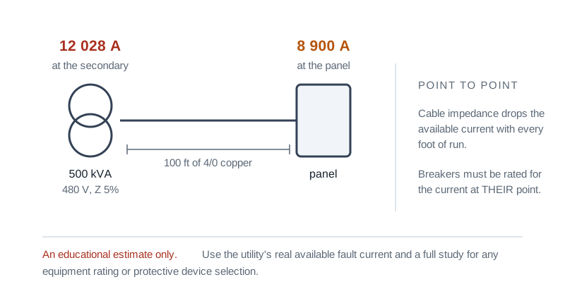
A simplified Bussmann / Cooper "point-to-point" calculation of the available short-circuit current at the transformer secondary and after an optional downstream cable. The result is a rough magnitude estimate: useful for sizing conversations, not for final protective-device coordination.
How to Use the Calculator
- 1Select 1-phase or 3-phase
- 2Enter transformer kVA rating
- 3Enter secondary line-to-line voltage
- 4Enter transformer %Z (impedance, typically 2 to 6%)
- 5Optionally enable a cable section and enter its length and approximate impedance per 1000 ft
- 6Read off the secondary FLA, available Isc, and the attenuated Isc at the fault point
Key features
Point-to-point method
The Cooper / Bussmann formula: Isc = I_FLA · (100/%Z), then M = 1/(1+f) for the cable
1-phase and 3-phase
Phase factor of 1 or √3 is applied automatically
Cable attenuation
Optional cable section reduces Isc via the M factor
Common AWG presets
One-click impedance values for 4/0, 2/0, #1, #4, #10 copper
Engineering disclaimer
Strong amber callout reinforcing that this is an estimate, not a design value
Live evaluation
Updates as you type: no submit button
Why a Short Circuit Estimator?
Every breaker downstream of a transformer must have an interrupting rating greater than the available fault current at its terminals. Underrated breakers can fail catastrophically during a fault. This tool gives a fast first-pass estimate so you can spot order-of-magnitude problems before requesting the formal study from a power-systems engineer.
Common use cases
- Sanity-check that a panel’s AIC rating exceeds the upstream fault current
- Quick estimate before requesting utility source impedance
- Compare two transformer sizes for the same downstream panel
- Teach the impact of cable length on available fault current
- Prepare context for a vendor / consultant conversation
Formulas
- I_FLA = (kVA · 1000) / (V · phase_factor), phase_factor = 1 for 1ph, √3 for 3ph
- Isc at transformer secondary: I_sc = I_FLA · (100 / %Z)
- Cable attenuation factor: f = (phase_factor · L · Ω/kft / 1000 · Isc) / V
- M = 1 / (1 + f)
- I_sc at fault point: I_sc · M
What is NOT modelled
Motor contribution to the fault, transformer X/R ratio (this is a magnitude-only estimate), utility source impedance (assumed infinite, i.e. worst case for the transformer), and arc-impedance effects. For protective-device coordination and arc-flash, use IEEE 1584 with a proper software study.
Tips & best practices
Smaller %Z = higher fault current
A 2% impedance transformer delivers roughly 50× its FLA into a bolted fault. A 6% transformer is closer to 17×. Spec the AIC of the panel accordingly.
Cable length is your friend
100 ft of #4 Cu can drop the available fault current by 30 to 50% downstream. This is why service-entrance gear is rated higher than a sub-panel at the end of a long feeder.
Motor contribution is real
Running motors briefly contribute their locked-rotor amps into a fault. For final coordination, add ~4× the largest motor’s FLA into the fault current calculation.
Privacy & security
Everything runs in your browser; no values leave your device.
Related tools
- Conduit Fill Calculator
NEC Chapter 9 conduit-fill calculator. Pick conduit type and trade size, add cables (THHN/THWN/XHHW by AWG), and get utilisation, NEC limit, and pass/fail.
Electronics & Embedded
- Resistor Color Code Decoder
Decode and encode 3, 4, 5, and 6-band resistor color codes. Pick colors to read the value, or enter a value to see the matching color bands.
Electronics & Embedded
- LED Resistor Calculator
Size the current-limiting resistor for a single LED, an LED chain in series, or several LEDs in parallel. Picks the nearest standard E-series value and recommends a safe wattage rating.
Electronics & Embedded
- Motor Full Load Current Calculator
Compute motor full-load current (FLA / FLC) for DC, single-phase, and three-phase motors from horsepower or kilowatts, efficiency, and power factor. Side-by-side NEC 430.250 reference.
Electronics & Embedded
- Ohm’s Law Calculator
Solve Ohm’s law for voltage, current, resistance, or power. Enter any two of V, I, R, and P and instantly get the other two with step-by-step derivations.
Electronics & Embedded
- Wire Size Calculator
NEC wire size calculator. Sizes copper or aluminum against Table 310.16 ampacity with ambient and conduit-fill derating, then against your voltage drop target, and reports which limit decided it.
Electronics & Embedded
Frequently Asked Questions
How accurate is the point-to-point method?
Accuracy is roughly ±10 to 20% for the transformer secondary number and degrades with cable length. It is sufficient for first-pass AIC checks but should NOT be used for protective-device coordination, arc-flash analysis, or formal study deliverables. For those use IEEE 1584, ANSI C37, or IEC 60909 with a documented impedance model.
Why does the tool not include motor contribution?
Motor contribution is a real second-order effect (about 4× the largest motor’s FLA, added to the bolted-fault current for the first cycle). It was deliberately omitted to keep the result a clear "lower bound." For final coordination, add motor contribution manually before comparing to breaker AIC ratings.
What %Z value should I use?
It comes from the transformer nameplate. Typical values are 2 to 3.5% for dry-type service transformers, 4 to 6% for liquid-filled, and up to 8 to 10% for very large units. If you don’t know, ask the manufacturer or the utility.
How does cable length affect fault current?
Cable adds impedance in series with the transformer. The point-to-point method captures this through the M factor: M = 1 / (1 + f), where f scales with length, conductor ohms/kft, and the available Isc at the source. For a 100 kVA / 480 V transformer with #4 Cu, 100 ft cable can drop Isc by ~30 to 50%.
What is AIC and why does it matter?
AIC: Ampere Interrupting Capacity, is the maximum fault current a breaker can interrupt safely. If the available short-circuit current at the breaker exceeds its AIC, the breaker can fail catastrophically during a fault. Every breaker downstream of the transformer must have AIC ≥ calculated Isc at its terminals.
Is anything sent to a server?
No: everything runs in your browser. No values, results, or interactions are uploaded.