PWM Duty & Frequency Calculator
Solve any unknown of a PWM waveform: frequency, period, duty cycle, on-time, off-time. Optional supply voltage gives average and RMS voltage. Inline waveform preview.
Interactive tool
Presets
Inputs
Fill any two of frequency / period / duty / tOn / tOff. Leave the others blank: the calculator will solve for them.
Result
What is the PWM Calculator?
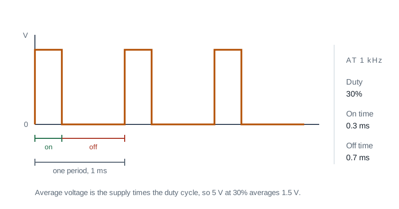
Pulse-Width Modulation (PWM) is a square wave whose duty cycle (the fraction of time the signal is high) carries the information. Servos read it as position, motor drivers as speed, LED drivers as brightness, and class-D amplifiers as audio. This calculator lets you solve any unknown of a PWM waveform from any consistent pair of inputs.
How to Use the Calculator
- 1Fill any two of: frequency, period, duty cycle, tOn, tOff
- 2Leave the others blank: the calculator solves for them
- 3Optionally enter Vmax to get the average and RMS voltage applied to a resistive load
- 4Use the preset chips for common designs (50 Hz servo, 1 kHz LED dim, 20 kHz motor PWM)
- 5The waveform preview shows the duty visually so you can sanity-check the result
Key features
Solve any unknown
Provide any two parameters; the rest are computed exactly
Average and RMS voltage
For a resistive load: V_avg = D·Vmax, V_rms = Vmax·√D
Common presets
Servo, LED, motor, switch-mode, audio class-D defaults
Visual waveform
Inline SVG shows the duty at a glance
Engineering notation
Input 1k, 100u, 500n: outputs in matching SI units
Live and private
Computed in your browser as you type; no data sent anywhere
Why a Dedicated PWM Calculator?
Datasheets quote PWM specs in mixed units: "20 kHz, 1500 µs pulse". You have to keep converting. Spelling out the relationship F·T=1, D=tOn/T, V_avg=D·Vmax in one place removes the busywork. The RMS voltage matters too: a 50%-duty PWM at 12 V doesn’t put 6 V across a heater. It puts 12/√2 ≈ 8.5 V RMS, which dissipates twice the power of a 6 V DC supply.
Common use cases
- Tune a servo signal (1.0 ms = full-left, 1.5 ms = centre, 2.0 ms = full-right at 50 Hz)
- Convert "70% duty at 20 kHz" to "tOn = 35 µs"
- Compute the heater power from a PWM-driven element at a given duty
- Pick a PWM frequency above the audible range (≥ 20 kHz) for silent motor drives
- Verify a switch-mode regulator timing waveform
- Estimate motor speed from PWM duty cycle
Core relationships
- f · T = 1
- Duty D = tOn / T = tOn / (tOn + tOff)
- tOn = D · T, tOff = (1 − D) · T
- For a resistive load: V_avg = D · Vmax
- For a resistive load: V_rms = Vmax · √D
- Power into a resistive load: P = D · Vmax² / R
Common frequency ranges
- 50 Hz: analog servos (RC, robotics)
- 100 Hz: 1 kHz, slow LED dimming (visible flicker possible)
- 1 kHz: 20 kHz, fast LED dimming, low-frequency motor control
- > 20 kHz: silent (above hearing); audio-band switching for motors and class-D
- 100 kHz: 2 MHz, switch-mode power supply (buck/boost) regulators
Resolution and timing
- PWM resolution = timer counts in one period; e.g. 8-bit PWM has 256 duty steps
- Higher frequency → fewer counts for a given timer clock → coarser resolution
- Trade-off: high frequency = silent + small filter caps; low frequency = finer steps
Tips & best practices
Choose frequency above 20 kHz for motors
A motor PWM’d at audible rates (1 to 10 kHz) whines loudly. 20 kHz or higher is silent and reduces switching losses are still acceptable on most MOSFETs.
Use the RMS, not the average, for heat calculations
A switched resistor (heater, motor coil) dissipates I²R·D. That equals (V·√D)²/R: the RMS voltage matters when sizing dump loads.
Watch for low-side vs high-side switching
A PWM’d MOSFET on the low side is easy. High-side switching (P-FET or charge-pump-driven N-FET) is harder: confirm gate-drive voltages.
Privacy & security
All calculations are performed in your browser.
Related tools
- Resistor Color Code Decoder
Decode and encode 3, 4, 5, and 6-band resistor color codes. Pick colors to read the value, or enter a value to see the matching color bands.
Electronics & Embedded
- LED Resistor Calculator
Size the current-limiting resistor for a single LED, an LED chain in series, or several LEDs in parallel. Picks the nearest standard E-series value and recommends a safe wattage rating.
Electronics & Embedded
- Motor Full Load Current Calculator
Compute motor full-load current (FLA / FLC) for DC, single-phase, and three-phase motors from horsepower or kilowatts, efficiency, and power factor. Side-by-side NEC 430.250 reference.
Electronics & Embedded
- Wire Size Calculator
NEC wire size calculator. Sizes copper or aluminum against Table 310.16 ampacity with ambient and conduit-fill derating, then against your voltage drop target, and reports which limit decided it.
Electronics & Embedded
- 555 Timer Calculator
Design an NE555 astable oscillator or monostable one-shot. Pick R1, R2, C and read off frequency, period, duty cycle, and pulse width, with an inline schematic.
Electronics & Embedded
- UPS Runtime Calculator
Estimate UPS / battery-backup runtime from battery voltage, capacity, series / parallel arrangement, load wattage, inverter efficiency, and depth of discharge. Includes a Peukert warning at high discharge rates.
Electronics & Embedded
Frequently Asked Questions
What is PWM duty cycle?
Duty cycle is the fraction of one period during which the signal is high, expressed as a percentage. A 25% duty PWM is high for 1/4 of each period, low for the rest.
How do I compute average voltage from PWM?
For a resistive load and a clean square wave, V_avg = duty · Vmax. A 12 V signal at 30% duty applies an average of 3.6 V.
Is RMS voltage the same as average?
No. For a square wave switching between 0 and Vmax, V_rms = Vmax · √duty. RMS matters for power dissipation: a 50% duty 12 V signal puts 12/√2 ≈ 8.5 V RMS across a heater, dissipating twice the power of a 6 V DC supply.
What frequency should I use for motor PWM?
For brushed DC motors, 16 to 20 kHz puts the switching above the audible range. Switching too fast (above ~30 kHz) increases MOSFET losses; switching too slow (below 10 kHz) makes the motor whine.
What about servo PWM?
Analog hobby servos take a 50 Hz signal (20 ms period). Pulse width 1.0 ms = full-left, 1.5 ms = centre, 2.0 ms = full-right. That works out to 5 to 10% duty cycle.
Is anything sent to a server?
No. All computation runs locally in your browser. No data is uploaded.