555 Timer Calculator
Design an NE555 astable oscillator or monostable one-shot. Pick R1, R2, C and read off frequency, period, duty cycle, and pulse width, with an inline schematic.
Interactive tool
Presets
Inputs
Result
What is the 555 Timer Calculator?
The NE555 is the most-cloned analog chip ever made: found in blinkers, debouncers, PWM controllers, monostable one-shots, and a thousand toys. This tool sizes the timing resistors and capacitor for the two canonical modes: astable (free-running oscillator) and monostable (single timed pulse).
How to Use the Calculator
- 1Pick astable for a continuous square wave; monostable for a single timed pulse
- 2Astable: enter R1, R2, and the timing cap C (read off frequency, period, duty cycle, tHigh and tLow)
- 3Monostable: enter R and C, read off the pulse width T = ln(3) · R · C ≈ 1.1·R·C
- 4Use the preset chips for common designs (1 Hz blinker, 1 kHz PWM, button debounce, etc.)
- 5Check the engineering notes for limits and caveats
Key features
Astable mode
f, T, duty, tHigh, tLow from R1, R2, C
Monostable mode
Pulse width T from R and C
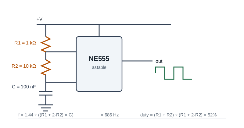
Inline schematic
Pin-out diagram that follows the selected mode
Real-world presets
1 Hz blinker, audio tone, PWM, debounce, slow timer
Engineering notation
Type 100n, 1u, 1M: auto-formatted output
100% client-side
Calculations run in your browser; nothing is uploaded
Why a Dedicated 555 Calculator?
The 555 formulas are simple but easy to get backwards. Astable duty cycle is always >50% in the standard wiring (because tHigh charges through R1+R2 but tLow discharges through R2 only). This tool surfaces that asymmetry, warns about regions where the standard NE555 misbehaves (sub-µs pulses, MHz oscillation, multi-minute timers), and points to better alternatives when relevant.
Common use cases
- Design an LED blinker for a status indicator
- Tune a 555-based PWM motor speed controller
- Generate a precision pulse for a sensor strobe
- Build a debounced switch input
- Generate an audible tone (1 to 5 kHz square)
- Teach analog timing on a breadboard
Astable formulas
- tHigh = ln(2) · (R1 + R2) · C
- tLow = ln(2) · R2 · C
- Period T = tHigh + tLow = ln(2) · (R1 + 2R2) · C
- Frequency f = 1 / T ≈ 1.44 / ((R1 + 2R2) · C)
- Duty cycle = (R1 + R2) / (R1 + 2R2)
Monostable formula
- Pulse width T = ln(3) · R · C ≈ 1.1 · R · C
- The trigger input (pin 2) must be pulsed low briefly to start the pulse
- The output (pin 3) goes high for T, then returns low until the next trigger
Practical limits
- R1 > 1 kΩ to avoid excess discharge current on pin 7
- R total < ~10 MΩ: leakage starts to dominate above this
- C from 100 pF up to ~10 µF works well; electrolytics drift with temperature
- For 50% duty astable, place a diode across R2 (anode at pin 7)
- Use LMC555 (CMOS) for low-power and frequencies above ~500 kHz
Tips & best practices
Pin 5 needs a decoupling cap
Tie pin 5 (control voltage) to ground through a 10 nF capacitor for low-noise operation.
Power supply decoupling
Put a 100 nF cap between Vcc (pin 8) and GND (pin 1) right next to the chip: the 555 has a noisy ground bounce on output transitions.
Output drive
The NE555 sinks/sources ~200 mA at the output. That’s enough for a small relay or several LEDs in parallel, but you may want a buffer for higher loads.
Privacy & security
All calculations are performed in your browser.
Related tools
- Power Calculator (DC, AC, 3-Phase)
Compute real, apparent, and reactive power for DC and AC circuits including single-phase and three-phase systems with adjustable power factor.
Electronics & Embedded
- PWM Duty & Frequency Calculator
Solve any unknown of a PWM waveform: frequency, period, duty cycle, on-time, off-time. Optional supply voltage gives average and RMS voltage. Inline waveform preview.
Electronics & Embedded
- Short Circuit Current Estimator
Educational point-to-point estimator for available short-circuit current from a transformer secondary, with optional cable attenuation. Not a replacement for IEEE 1584 or utility-provided fault values.
Electronics & Embedded
- Cable Tray Fill Calculator
NEC 392.22 cable tray fill check for ladder, ventilated, and solid-bottom trays. Sums cable areas / diameters and reports pass/fail with the right rule citation.
Electronics & Embedded
- RC Time Constant Calculator
Compute the time constant τ = R × C, plot the charge or discharge curve, and find the time to reach a target voltage for any RC circuit.
Electronics & Embedded
- Signal Attenuation (dB) Calculator
Convert between power / voltage ratios and dB, compute Free-Space Path Loss (FSPL), and estimate cable attenuation. Supports forward and reverse calculations.
Electronics & Embedded
Frequently Asked Questions
What is the frequency formula for a 555 astable?
f = 1.44 / ((R1 + 2 · R2) · C). Equivalently, tHigh = ln(2) · (R1+R2) · C and tLow = ln(2) · R2 · C, and the period is their sum.
Why can’t I get exactly 50% duty cycle?
In the standard astable wiring, the cap charges through R1+R2 (tHigh) but discharges through R2 alone (tLow), so duty is always > 50%. For a true 50% duty, put a diode across R2 with the anode at pin 7, or use a CMOS variant with a separate discharge path.
What is the monostable pulse-width formula?
T = ln(3) · R · C, which is approximately 1.1 · R · C. The pulse begins when pin 2 (TRIGGER) is briefly pulled below 1/3 Vcc and ends when the cap on pin 6 charges back up to 2/3 Vcc.
What are practical R and C ranges?
Keep R between 1 kΩ and ~10 MΩ to balance discharge current and leakage. C from 100 pF up to a few µF works well. Electrolytic caps drift with temperature: use film or ceramic for stable timing.
Is the NE555 good above 100 kHz?
The bipolar NE555 starts to degrade above a few hundred kHz. Use the CMOS LMC555 or TLC555 for low power and frequencies into the MHz range.
Is anything sent to a server?
No. All math runs locally in your browser. No values are uploaded.