Power Factor Correction Calculator
Compute kVAR and capacitance per phase needed to raise an installation from its current power factor to a target. Before/after power-triangle diagram and current-reduction estimate.
Interactive tool
Presets
Inputs
Result
What is the Power Factor Correction Calculator?
Given the real power and the current (uncorrected) power factor of an installation, this tool computes the reactive power (kVAR) and per-phase capacitance (µF) of the correction capacitors needed to lift the power factor to a target. It also shows the resulting line-current reduction: the main reason utilities charge for low PF.
How to Use the Calculator
- 1Select 1-phase or 3-phase (for 3-phase, also pick delta or wye capacitor connection)
- 2Enter real power P (accepts engineering notation, e.g. 100k for 100 kW)
- 3Enter the current power factor (the value reported by the utility or measured PF meter)
- 4Enter the target power factor (utility tariffs typically penalise below 0.90 to 0.95)
- 5Enter line voltage and frequency (60 Hz for North America, 50 Hz elsewhere)
- 6Read off the required kVAR, capacitor microfarads per phase, and current reduction
Key features
1-phase and 3-phase
Delta or wye capacitor connections supported; delta is more economical
Power-triangle diagram
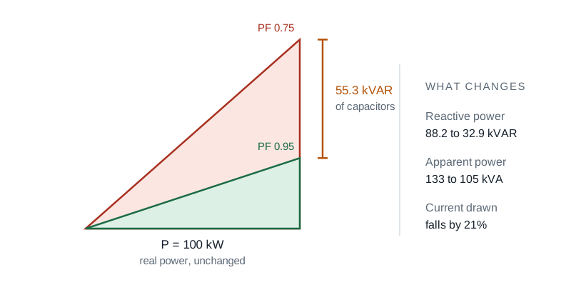
Before/after triangle visualises the reactive-power reduction
Current reduction
Tells you how many amps you save on the supply conductors
Engineering notation
Enter P as 100k, 1.5M, etc.
Common presets
Industrial, IEC, North American, and MV scenarios
Engineering disclaimer
Calls out harmonics and detuning as real-world considerations
Why Power Factor Correction Matters
Reactive current does no useful work but still flows through every conductor, transformer, and breaker between the utility and the load. Low PF means oversized cables, oversized transformers, and: above some threshold, utility penalties on the bill. Correction capacitors locally supply the reactive current, removing it from the upstream system. The economic payback for industrial sites with PF below 0.85 is often under two years.
Common use cases
- Spec a capacitor bank for an industrial site to avoid the utility kVAR penalty
- Size correction at a single induction-motor load
- Compare delta vs wye bank cost for the same reactive demand
- Estimate line-current reduction in feeder conductors
- Sanity-check a vendor quote against the textbook calculation
Formulas
- Q_existing = P · tan(acos(PF_current))
- Q_target = P · tan(acos(PF_target))
- Q_needed = Q_existing − Q_target
- 1-phase: C = Q / (2π · f · V²)
- 3-phase Δ: C = Q / (3 · 2π · f · V_LL²)
- 3-phase Y: C = Q / (2π · f · V_LL²)
Delta vs wye
Delta-connected caps see V_LL across each capacitor, so the required capacitance per phase is 1/3 of the wye-connected equivalent for the same reactive power. Delta is therefore the standard choice for industrial banks. Wye is occasionally used for fixed compensation of star-point loads.
Sizing a capacitor bank
- Work from measured demand rather than nameplate ratings, because motors on light load have a far worse power factor than their plate suggests.
- Correct at the load for a single large motor, or at the panel for a mixed installation. Correcting at the load also unloads the feeder that serves it.
- Switch the bank in steps rather than as one block, so light load periods do not swing the installation into a leading power factor.
- Check for harmonics before installing capacitors. A capacitor bank and the supply inductance form a resonant circuit, and on a supply with significant harmonic content that resonance can amplify them badly. Detuned reactors exist for exactly this case.
Capacitor kVAR needed per kW of load
Multiply your real power in kW by the figure below to get the capacitor kVAR needed to reach a target power factor of 0.95. A 200 kW load at 0.80 needs 200 x 0.421, which is about 84 kVAR.
| Starting power factor | kVAR per kW to reach 0.95 | For a 100 kW load |
|---|---|---|
| 0.70 | 0.692 | 69.2 kVAR |
| 0.75 | 0.553 | 55.3 kVAR |
| 0.80 | 0.421 | 42.1 kVAR |
| 0.85 | 0.291 | 29.1 kVAR |
| 0.90 | 0.156 | 15.6 kVAR |
The figures are tan(acos(starting PF)) minus tan(acos(0.95)). Correcting beyond about 0.95 rarely pays for itself, and overcorrecting into a leading power factor can cause overvoltage and resonance with harmonics on the system.
Tips & best practices
Don’t overcorrect
Leading PF stresses the supply and the capacitors themselves. Aim for a target slightly below unity (0.95 to 0.98) and use detuning reactors in harmonic-rich environments.
Watch out for resonance
A bare capacitor bank can resonate with the supply transformer’s leakage inductance at a harmonic, causing destructive currents. Detuning reactors push the resonance below the lowest dominant harmonic (usually the 5th).
Automatic banks for variable loads
If the reactive demand changes through the day, an automatic capacitor bank with multiple stages and contactors avoids overcorrection at light load.
Privacy & security
Everything runs in your browser; no values leave your device.
Related tools
- Power Calculator (DC, AC, 3-Phase)
Compute real, apparent, and reactive power for DC and AC circuits including single-phase and three-phase systems with adjustable power factor.
Electronics & Embedded
- Voltage Drop Calculator
NEC voltage drop calculator. Enter system, voltage, current, one-way length and conductor, and get volts dropped, percent drop, voltage at the load and the smallest conductor that meets your target.
Electronics & Embedded
- Conduit Fill Calculator
NEC Chapter 9 conduit-fill calculator. Pick conduit type and trade size, add cables (THHN/THWN/XHHW by AWG), and get utilisation, NEC limit, and pass/fail.
Electronics & Embedded
- Signal Attenuation (dB) Calculator
Convert between power / voltage ratios and dB, compute Free-Space Path Loss (FSPL), and estimate cable attenuation. Supports forward and reverse calculations.
Electronics & Embedded
- ADC / DAC Converter Calculator
Convert between analog voltage and digital code for any N-bit ADC or DAC. Computes LSB size, quantisation error, full-scale range, and ideal dynamic range (SQNR).
Electronics & Embedded
- Capacitor Charge & Energy Calculator
Compute the stored charge (Q = CV) and energy (E = ½ CV²) of a charged capacitor, with intuitive real-world comparisons.
Electronics & Embedded
Frequently Asked Questions
How do I calculate the kVAR needed for power factor correction?
Q_needed = P · (tan(acos(PF_current)) − tan(acos(PF_target))). For example, 100 kW at PF 0.7 brought to 0.95 requires about 69 kVAR. The capacitor banks supply that reactive power locally so it doesn’t flow back to the utility.
Delta or wye capacitor connection?
Delta is the standard choice in industrial installations. Capacitors see V_LL across each unit, so the per-phase capacitance is 1/3 of an equivalent wye bank. Wye is occasionally used for fixed compensation tied to a star-point load.
Why does utility charge for low power factor?
Low PF means the utility has to deliver more apparent power (kVA) than the real-power (kW) revenue justifies. The extra current also stresses transformers and feeders. Most tariffs include a kVAR charge or a kVA demand charge above some PF threshold (often 0.90 or 0.95).
Can I overcorrect?
Yes: a permanently leading PF stresses the supply and the capacitors. Aim slightly below unity (0.95 to 0.98), and use automatic banks if the reactive load varies through the day.
What about harmonics?
A bare capacitor bank can resonate with the supply transformer’s leakage inductance at a harmonic frequency, causing destructive overvoltages and currents. Detuned banks add a series reactor to push the resonance below the lowest dominant harmonic (typically the 5th).
Is anything sent to a server?
No: everything runs in your browser. No values, results, or interactions are uploaded.
How do I calculate kVAR from kW and power factor?
Reactive power is real power multiplied by the tangent of the angle whose cosine is the power factor: kVAR equals kW times tan(acos(PF)). At 100 kW and a power factor of 0.80 that is 75 kVAR. To correct, subtract the kVAR you want from the kVAR you have.
What size capacitor bank do I need?
Multiply your real power in kW by the factor in the table above for your starting power factor. Going from 0.80 to 0.95 needs 0.421 kVAR per kW, so a 200 kW load needs roughly 84 kVAR. Size from measured demand rather than nameplate, and switch the bank in stages.