Wire Size Calculator
NEC wire size calculator. Sizes copper or aluminum against Table 310.16 ampacity with ambient and conduit-fill derating, then against your voltage drop target, and reports which limit decided it.
Interactive tool
Presets
Load and conditions
Voltage drop
Result
What is the Wire Size Calculator?
A conductor has to satisfy several limits at once, and the correct size is whichever limit demands the most copper. This calculator applies all of them: the Table 310.16 ampacity, the ambient temperature correction, the adjustment for bundled conductors, the termination temperature ceiling in NEC 110.14(C), the small-conductor overcurrent limits in 240.4(D), and your voltage drop target. It returns one size, and it tells you which limit decided it.
How to Use the Wire Size Calculator
- 1Enter the load current in amperes, and tick continuous if the load runs for three hours or more
- 2Pick copper or aluminum, and the insulation rating of the conductor you intend to use
- 3Set the termination rating. Equipment terminals are commonly 60 °C at 100 A or less and 75 °C above, whatever the wire is rated
- 4Enter the ambient temperature if it is not the 30 °C the tables assume. An attic or a boiler room is not 30 °C
- 5Enter how many current-carrying conductors share the raceway, so the bundling adjustment applies
- 6Add the system, voltage and one-way length to include voltage drop, or leave all three out to size on ampacity alone
Key features
NEC Table 310.16
Ampacities at 60, 75 and 90 °C for copper and aluminum, straight from the table
Termination ceiling
Applies 110.14(C), the rule most calculators skip and the usual cause of an undersized answer
Small conductor limits
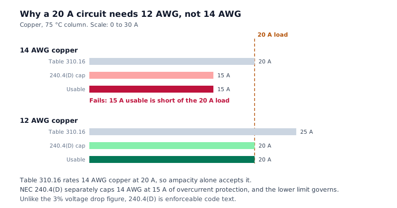
240.4(D) caps 14 AWG copper at 15 A regardless of ampacity, so a 20 A circuit gets 12 AWG
Ambient and bundling
Both derating factors apply, and they stack rather than replacing one another
Voltage drop together with ampacity
Sizes against both limits and names which one decided
Shows its working
Every candidate size, its table ampacity, each ceiling and the usable figure
Why Sizing on Ampacity Alone Goes Wrong
The ampacity table is the part everybody knows, and on its own it is not enough. Three separate rules can force a larger conductor than the table suggests, and each has its own failure mode. Skipping the termination rule in 110.14(C) returns a conductor one size too small, because 90 °C wire terminating on 75 °C lugs does not get to use its own column. Skipping 240.4(D) puts a 20 A circuit on 14 AWG, which is the classic residential error. Skipping derating hides the fact that a full conduit in a hot space loses a third of its rating. This calculator applies all of them and reports which one bound the result.
Common use cases
- Size a branch circuit correctly and see whether ampacity or drop set the answer
- Size a feeder to a subpanel, including the run length
- Check whether an existing conductor is adequate at the ambient it actually runs in
- Work out what a full conduit costs you in conductor size
- Compare copper against aluminum for the same load and run
- Confirm a 20 A receptacle circuit needs 12 AWG and understand exactly why
The three ceilings, and why all of them apply
- Start with the ampacity from Table 310.16 for the conductor’s own temperature rating. Multiply by the ambient correction from Table 310.15(B)(1), then by the bundling adjustment from 310.15(C)(1) if more than three current-carrying conductors share the raceway. That gives the derated ampacity.
- Then apply NEC 110.14(C). Equipment terminations have their own temperature rating, usually 60 °C for circuits at 100 A or less and 75 °C above, and the conductor may not be used above the ampacity of that column no matter how good its insulation is. A 90 °C conductor derates on the 90 °C column and is then capped at the 75 °C figure. Using the 90 °C column end to end is the single most common way a wire size comes out one size too small.
- Finally apply NEC 240.4(D). For 14, 12 and 10 AWG the overcurrent protection is capped below the table ampacity: 15, 20 and 30 A for copper, and 15 and 25 A for 12 and 10 AWG aluminum. This is why 14 AWG copper, which Table 310.16 rates at 20 A, cannot serve a 20 A circuit. Unlike the 3% voltage drop figure, this one is enforceable code text rather than an Informational Note.
- The usable ampacity is the smallest of those three results, and the correct conductor is the first size whose usable ampacity meets the load.
Continuous loads and the 125% factor
- A continuous load is one expected to run at its maximum for three hours or more. NEC 210.19(A) and 215.2(A) require the conductor to be sized at 125% of the continuous portion, which is why a 40 A continuous load is sized as 50 A.
- The reason is thermal. A conductor at its rated ampacity is at its rated temperature only once it has reached equilibrium, and three hours is roughly where that happens. A load that cycles never gets there. Lighting circuits, EV chargers, electric heating and most commercial loads are continuous; a domestic receptacle circuit generally is not.
Why ampacity and voltage drop disagree
- Ampacity is about heat, and heat depends on current, not distance. Voltage drop is about resistance over length, so it grows with the run while ampacity does not move at all. On a short run ampacity almost always decides. Past roughly 100 feet at typical branch-circuit currents, drop starts to take over, and on a long run it can demand two or three sizes more than the thermal limit.
- This is why sizing on ampacity alone is safe but not sufficient, and why a conductor that passes inspection can still leave a motor running badly at the far end. Give the calculator the run length and it will report which limit bound the result, so you know whether the fix is a bigger conductor or a shorter route.
NEC Table 310.16 ampacity, copper and aluminum
Allowable ampacity at 30 °C ambient with not more than three current-carrying conductors in a raceway. These are the starting figures, before any derating and before the 110.14(C) and 240.4(D) ceilings.
| Size | Cu 60 °C | Cu 75 °C | Cu 90 °C | Al 60 °C | Al 75 °C | Al 90 °C |
|---|---|---|---|---|---|---|
| 14 AWG | 15 | 20 | 25 | n/a | n/a | n/a |
| 12 AWG | 20 | 25 | 30 | 15 | 20 | 25 |
| 10 AWG | 30 | 35 | 40 | 25 | 30 | 35 |
| 8 AWG | 40 | 50 | 55 | 35 | 40 | 45 |
| 6 AWG | 55 | 65 | 75 | 40 | 50 | 55 |
| 4 AWG | 70 | 85 | 95 | 55 | 65 | 75 |
| 2 AWG | 95 | 115 | 130 | 75 | 90 | 100 |
| 1/0 AWG | 125 | 150 | 170 | 100 | 120 | 135 |
| 2/0 AWG | 145 | 175 | 195 | 115 | 135 | 150 |
| 4/0 AWG | 195 | 230 | 260 | 150 | 180 | 205 |
| 250 kcmil | 215 | 255 | 290 | 170 | 205 | 230 |
| 500 kcmil | 320 | 380 | 430 | 260 | 310 | 350 |
Aluminum is not tabulated at 14 AWG. Remember that 240.4(D) separately caps 14, 12 and 10 AWG below these figures, so the 20 A shown for 14 AWG copper is not usable as 20 A of overcurrent protection.
Tips & best practices
Read the termination rating off the equipment
It is stamped on the breaker and the lug, not on the wire, and it is frequently the limit that binds. 90 °C wire on 75 °C lugs is a 75 °C circuit.
Count only current-carrying conductors
Grounds do not count toward the bundling adjustment, and the neutral of a balanced three-phase circuit generally does not either.
Ambient is at the raceway
Not the room average. An attic in summer, a conduit on a south wall and a boiler room are all well above the 30 °C the tables assume.
If drop decided it, check the route first
Voltage drop scales with length, so a shorter path can be cheaper than two conductor sizes. The result tells you which limit bound it.
Size on ampacity alone deliberately
It is a legitimate choice for a short run. Untick the drop check on purpose rather than by leaving the length blank and assuming it was considered.
Privacy & security
Every calculation runs in your browser. Nothing about your circuit, your load or your project is uploaded, stored or logged.
Frequently asked questions
What size wire do I need for a 20 amp circuit?
+
12 AWG copper. Table 310.16 rates 14 AWG copper at 20 A, which makes it look adequate, but NEC 240.4(D) caps 14 AWG at 15 A of overcurrent protection regardless of that ampacity. 12 AWG is capped at 20 A and so is the smallest conductor that can serve the circuit. This is the most common sizing mistake in residential work.
What size wire do I need for 50 amps? For 100 amps?
+
For 50 A on 75 °C copper with 75 °C terminations at normal ambient, 8 AWG carries exactly 50 A and qualifies. For 100 A, 3 AWG copper is the first size that reaches 100 A on the 75 °C column. Both answers change once you add ambient temperature, bundled conductors or a long run, which is what the calculator is for.
Why can 14 AWG not be used on a 20 amp circuit?
+
Because ampacity and overcurrent protection are two different limits. Table 310.16 gives 14 AWG copper 20 A of ampacity, and NEC 240.4(D)(3) separately limits it to 15 A of overcurrent protection. The lower limit governs. Unlike the 3% voltage drop guidance, 240.4(D) is enforceable code text rather than an Informational Note.
What is the 125% continuous load rule?
+
A continuous load is one expected to run at maximum for three hours or more. NEC 210.19(A) and 215.2(A) require the conductor to be sized at 125% of that portion, so a 40 A continuous load is sized as 50 A. The reason is thermal: a conductor only reaches its rated temperature after running for a few hours, so a load that cycles never gets there and a load that does not, does.
What is the NEC 110.14(C) termination rule?
+
Equipment terminals have their own temperature rating, commonly 60 °C for circuits at 100 A or less and 75 °C above. A conductor may be derated on its own temperature column but may not be used above the ampacity shown in the termination column. So 90 °C wire landing on 75 °C lugs is capped at the 75 °C figure. Using the 90 °C column end to end is the usual reason a calculated size comes out one size too small.
Does ambient temperature change the wire size?
+
Yes, and often by a full size. The ampacity tables assume 30 °C. At 45 °C a 75 °C conductor keeps only 82% of its rating, so a 45 A load that fits on 8 AWG at normal ambient needs 6 AWG in a hot attic. Ambient means the temperature around the raceway, not the average room temperature.
How many wires in a conduit before derating applies?
+
More than three current-carrying conductors triggers the NEC 310.15(C)(1) adjustment: 80% for 4 to 6, 70% for 7 to 9, 50% for 10 to 20, and lower beyond that. Grounds do not count, and the neutral of a balanced three-phase circuit generally does not either. The adjustment stacks with the ambient correction rather than replacing it.
Should I size wire for ampacity or for voltage drop?
+
Both, and take whichever demands more. Ampacity is about heat and does not change with distance; voltage drop grows with the length of the run. On a short run ampacity almost always decides. Past roughly 100 feet at typical branch-circuit currents, drop takes over and can demand two or three sizes more. Sizing on ampacity alone is safe but frequently leaves equipment running badly at the far end.
Related tools
- Voltage Drop Calculator
NEC voltage drop calculator. Enter system, voltage, current, one-way length and conductor, and get volts dropped, percent drop, voltage at the load and the smallest conductor that meets your target.
Electronics & Embedded
- Conduit Fill Calculator
NEC Chapter 9 conduit-fill calculator. Pick conduit type and trade size, add cables (THHN/THWN/XHHW by AWG), and get utilisation, NEC limit, and pass/fail.
Electronics & Embedded
- Resistor Color Code Decoder
Decode and encode 3, 4, 5, and 6-band resistor color codes. Pick colors to read the value, or enter a value to see the matching color bands.
Electronics & Embedded
- LED Resistor Calculator
Size the current-limiting resistor for a single LED, an LED chain in series, or several LEDs in parallel. Picks the nearest standard E-series value and recommends a safe wattage rating.
Electronics & Embedded
- Motor Full Load Current Calculator
Compute motor full-load current (FLA / FLC) for DC, single-phase, and three-phase motors from horsepower or kilowatts, efficiency, and power factor. Side-by-side NEC 430.250 reference.
Electronics & Embedded
- Unicode Converter
Convert text to and from Unicode escapes, code points, UTF-8 hex bytes, and Unicode normalization forms
Encoding Tools